
The following reference materials are as follows: (1) description of article 3.4.4 of code for seismic design of buildings dgj08-9-2013 of Shanghai Engineering Construction Code: Figure 4-1 (2) seismic design diagram of transfinite high-rise buildings in Sichuan Province: Although the provisions of the two materials are not completely the same, However, the concept is basically the same.

After manual review, the correct displacement ratio between two layers should be, while the displacement ratio calculated by yjk software is yjk.

eight Summary of displacement ratio: (1) the displacement ratio can be calculated by block rigid slab, not limited to the assumption of full floor rigid slab of the calculation model.
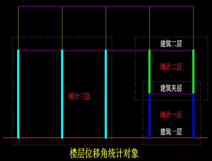
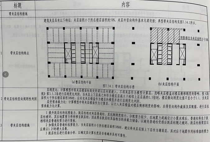
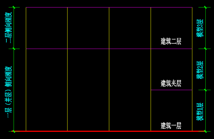
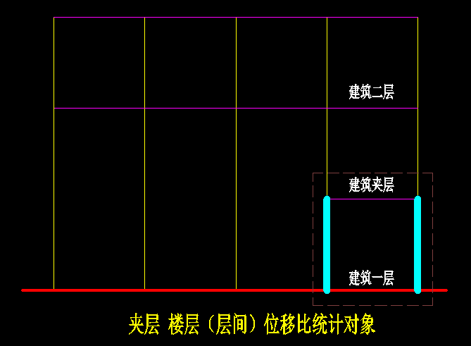
four When the proportion of mezzanine plane area to the first floor plane area is different, the index statistical methods are also different.
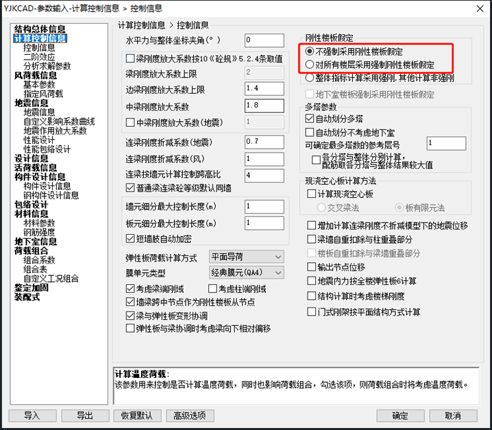
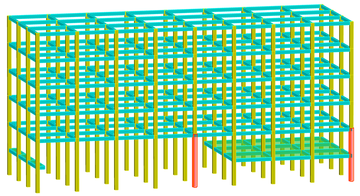
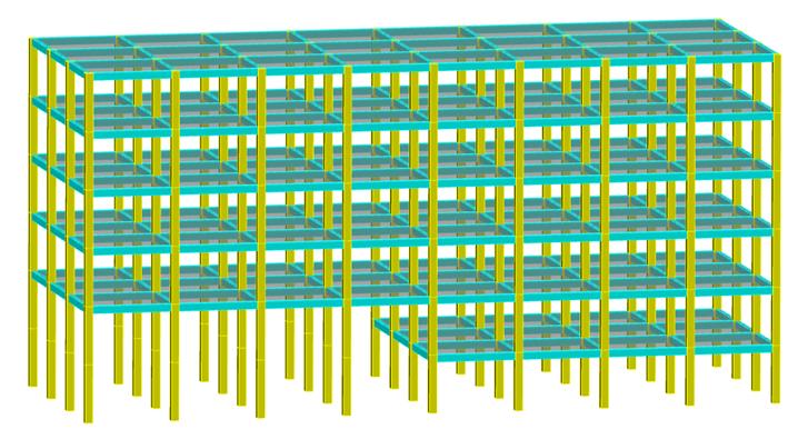
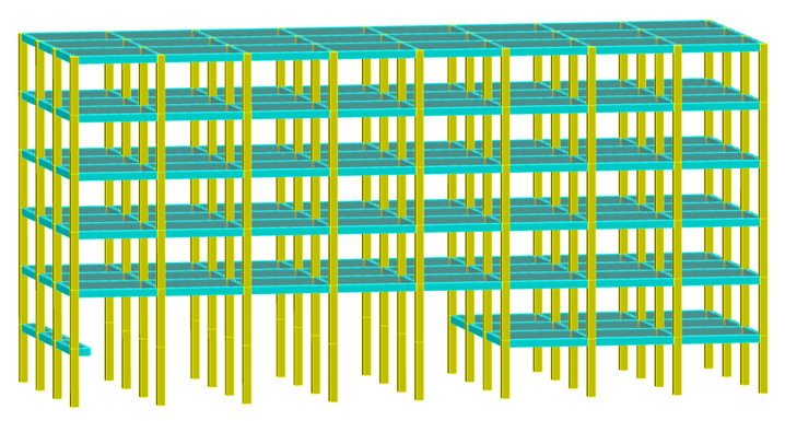
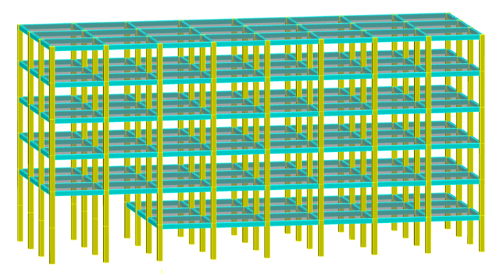
six A simple calculation example is used to illustrate the calculation conditions as follows: (1) the height of each layer is 4000mm, a total of 6 layers (including interlayer), and the column grid size is 6000mm x 6000mm; (2) The column section size is 500mmx500mm, the beam section is 250mx500mm, and the plate thickness is 120mm; (3) The strength grade of beam, slab and column concrete is C30; (4) On line load of beam is 10kN / m, dead load of slab is 1.5kpa, live load is 2.5kpa, basic wind pressure is 0.65kpa, class B site; (5) Ground motion parameters: 7 degrees 0.1g, a group of class II sites; (6) The 3D view of the model is shown in the figure below; (7) Select “do not force rigid floor slab assumption” in software parameter setting to ensure that it is block rigid slab instead of full floor rigid slab assumption; seven The calculation results of yjk software’s displacement ratio are as follows.
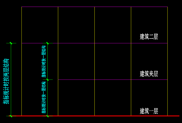
When the area of mezzanine accounts for a small proportion, as shown in the 1-3 three-dimensional view, the mezzanine cannot be calculated as one structural layer in index statistics, and the mezzanine under and on the mezzanine floor should be combined into one structural layer, as shown in Figure 4-2; When the proportion of mezzanine is relatively large, as shown in the 3D view 1-1, the lower part of mezzanine floor and the upper part of mezzanine floor are treated as a structural layer respectively, as shown in Figure 4-3.
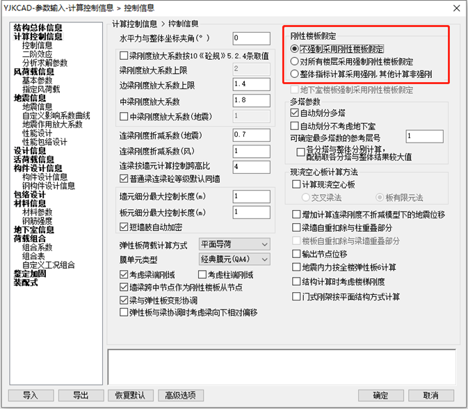
Figure 5-3 figure 5-4 figure 5-5 in combination with the above, the displacement ratio can be calculated by block rigid plate, but not limited to the assumption of the whole floor rigid plate of the calculation model, such as 3D view 1-4, the displacement ratio measurement at the mezzanine floor, the displacement ratio shall be calculated according to the left and right rigid floors respectively, and “do not force the assumption of rigid floor” shall be selected in the software parameter setting, The block rigid floor function is specified in the preprocessing slab properties.
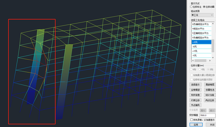
The maximum displacement is 8.28-3.45 = 4.83mm and the minimum displacement is 5.73-2.31 = 3.42mm.
5-3 add two X positive horizontal forces of 500kN on the top of two columns, FIG.
Therefore, the displacement ratio of each rigid plate needs to be manually reviewed, rather than the software calculation results.
5-4 shows the horizontal displacement calculated by using the parameter of “no mandatory rigid floor assumption”, and Fig.

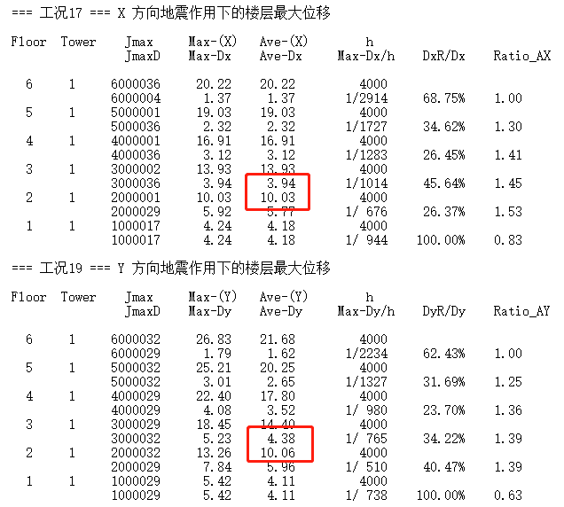
The correct displacement ratio of the interlayer only needs to count the BCDE area, and extract the positive deviation of the interlayer y to the specified horizontal force and the horizontal displacement in the Y direction, as shown in the figure below: Through manual review, the correct displacement ratio between mezzanine floors and between floors should be, while the displacement ratio calculated by yjk software is yjk software.
Extract the horizontal displacement in Y direction of positive deviation specified horizontal force of layer II and interlayer y, as shown in the following figure: Calculation of second floor displacement ratio: the calculation object is the two cyan columns in the left figure of the above figure.
Figure 4-2 Figure 4-3 Displacement ratio five For the assumption requirements for the calculation of displacement ratio, refer to some specifications, such as article 3.4.4 of Guangdong standard technical specification for concrete structures of high rise buildings DBJ / t15-92-2021, as shown in Figure 5-1; Article 3.4.3 of code for seismic design of buildings (gb50011-2010), as shown in Figure 5-2; Article 3.4.4 of code for seismic design of buildings (dgj08-9-2013) of Shanghai engineering construction code is shown in Figure 4-1.
The two calculation results are completely different, and the influence of different calculation assumptions on the calculation results should be realized in the design, It depends on the actual situation.

Star setting: enter the official account homepage, click the “top” corner, click “set star”, and the official account will appear yellow Pentagram (Android (same as IOS user operation) overview one As required by the building function, a mezzanine is set at the position about the middle floor height of the first floor with a relatively high height.


5-2, FIG.

5-1, FIG.

The proportion of the mezzanine plane area to the first floor plane area varies, as shown in the following figure: Figure 1-1, Figure 1-2, figure 1-31-42 In the structural design, some overall indicators of the structure in the code are based on the “floor”, which requires that the natural floor slab is basically complete and has a certain in-plane stiffness to coordinate the joint work of various vertical components, and the vertical components of the natural floor are considered as a whole; three For the “lateral stiffness ratio”, “displacement ratio” and “shear bearing capacity ratio” and other indicators in the code, the “layer” is taken as the benchmark.
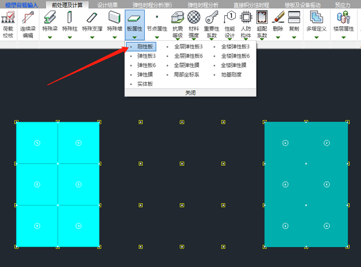
The function of block rigid slab is specified in the pre-treatment slab attribute (the slab is rigid slab by default).
The result is incorrect because the plane range counted by the software is incorrect.
5-5 shows the horizontal displacement calculated by using the parameter of “mandatory rigid floor assumption for all floors”.

Because the official account official has adjusted the push rules, if you want to continue to receive the contents of the official account, please set the public building number of the building as the star sign, and more points of the “look at” and “praise” in the end of the article.
(2) For the displacement ratio measurement of sandwich structure, only the area with floor slab needs to be counted, and the area without floor slab and only column joints does not need to be counted.
The maximum displacement is 12.53mm, the minimum displacement is 5.73mm, and the displacement ratio of the second floor calculated by yjk software is also 1.37, which are equal, because the plane range of manual and software statistics is consistent.

For the structure with no obvious “layer”, the statistical indicators have no substantive significance.
“If you want to continue to receive the official account, please note that the” WeChat “is a public key.
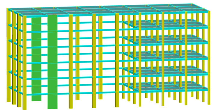
Fig.

Calculation of weighing ratio between two floors: the calculation object is the two cyan columns in the right figure of the above figure, which should correspond to the scope of the lower floor.
For the interlayer, the displacement ratio counted by yjk software includes the ACDF area, which is meaningless.
The result is incorrect because the plane range counted by the software is incorrect.
Lateral stiffness ratio nine When the proportion of the interlayer area is small, the lateral stiffness of the combined layer shall be adopted, that is, the lower layer of the interlayer floor and the upper layer of the interlayer floor shall be combined into one layer to calculate the lateral stiffness, and then compared with the lateral stiffness of the upper layer, but the lateral stiffness of the interlayer and the upper layer cannot be compared, as shown in the following figure: Layered model method of lateral stiffness ratio: the interlayer is input as a standard layer, and the lateral stiffness ratio needs to be manually rechecked..