2
. 
The thickness of diaphragm wall is 1.2m and the wall depth is 57.5m
. 
When designing the diaphragm wall, the depth of soil penetration should be determined according to the hydrogeological conditions below the basement and the groundwater control
. 
As a retaining structure, the penetration depth of diaphragm wall should meet the requirements of stability and strength
.
The design and calculation of normal section bending, compression and inclined section shear bearing capacity and reinforcement of diaphragm wall shall comply with the relevant provisions of current national standard code for design of concrete structures (GB 50010)
.
In the soft soil layer, the embedded depth of diaphragm wall under the base is generally close to or greater than the excavation depth to meet the stability requirements
.
When the soil (rock) layer with good physical and mechanical properties such as dense sand layer or rock layer is below the base, the embedded depth of diaphragm wall below the base can be greatly shortened
.
The elevation of the top of the wall and the concrete strength of the wall after removing the laitance layer should meet the design requirements
.
The common wall thickness of underground continuous wall is 0.6, 0.8, 1.0 and 1.2m
.
In order to cut off the second confined water, the bottom of the diaphragm wall needs to enter the (8C) silty clay layer, and the depth below the base needs to reach 23.7m
.
Many factors need to be considered when determining the plane shape and groove width of diaphragm wall unit groove section, such as the structural stress characteristics of the wall section, the stability of the groove wall, the protection requirements of the surrounding environment and the construction conditions, etc
.
2、 The penetration depth of diaphragm wall is generally in the range of 10-50m, and the maximum depth can reach 150m
.
The design strength grade of diaphragm wall concrete shall not be lower than C30, and the concrete strength grade shall be increased according to relevant specifications when pouring underwater
.
1
.
Considering the water resisting effect, the depth of soil penetration should be determined as the water resisting curtain
.
In a specific project, the thickness of diaphragm wall should be determined according to the specifications of grooving machine, the requirements of impermeability of wall, the calculation of stress and deformation of wall
.
The excavation depth of the foundation pit of Shanghai World Expo 500kV underground substation is 34m
.
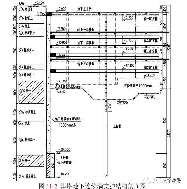
The excavation depth of Tianjin Jinta foundation pit is 22.1m, and 1.0m thick “two walls in one” diaphragm wall is used as enclosure
.
When the diaphragm wall is used as the main structure in the normal use stage, the reinforcement calculation should be carried out according to the limit state of normal use and the crack control requirements
.
As the retaining structure of foundation pit, the design and calculation of diaphragm wall are mainly based on the strength, deformation and stability
.
The soft plastic clay layer is mainly below the base
.
1、 The thickness of diaphragm wall is generally 0.5-1.2m
.
According to the stability calculation, the diaphragm wall inserted 17.2m below the base can meet the stability requirements
.
The section bearing capacity and reinforcement calculation of diaphragm wall should be carried out according to the internal force calculation envelope diagram of each working condition
.
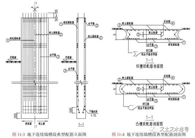
The protective layer of main reinforcement of diaphragm wall should not be less than 50 mm inside the foundation pit and 70 mm outside the foundation pit
.
The concrete pouring surface of the diaphragm wall should be 300-500mm higher than the design elevation
.
The normal section bending and inclined section shear bearing capacity of diaphragm wall should be checked, and the vertical compression bearing capacity should be checked when it needs to bear vertical load
.
When the groundwater control requirements require to cut off the groundwater or increase the groundwater flow path, the bottom of the diaphragm wall needs to enter the water resisting layer to cut off the hydraulic connection between the phreatic water and confined water inside and outside the pit, or insert Sufficient depth below the base to ensure a reliable barrier
.
The excavation depth of Nanjing Greenland Zifeng building is about 21.4m, and the underground continuous wall is embedded 7m below the base, which meets the stability requirements
.
The retaining structure adopts 130m diameter cylindrical diaphragm wall
.
For the cylindrical diaphragm wall, in addition to the normal section bending, oblique section shear and vertical compression bearing capacity checking calculation, it also needs the circumferential compression bearing capacity checking calculation
.
The main aspects of diaphragm wall design are described in detail below
.
When the diaphragm wall is only used as the retaining structure of foundation pit, the reinforcement calculation should be carried out according to the limit state of bearing capacity
.
The project has been completed, and the plain concrete section in the lower part of the diaphragm wall has effectively cut off the second confined water
.
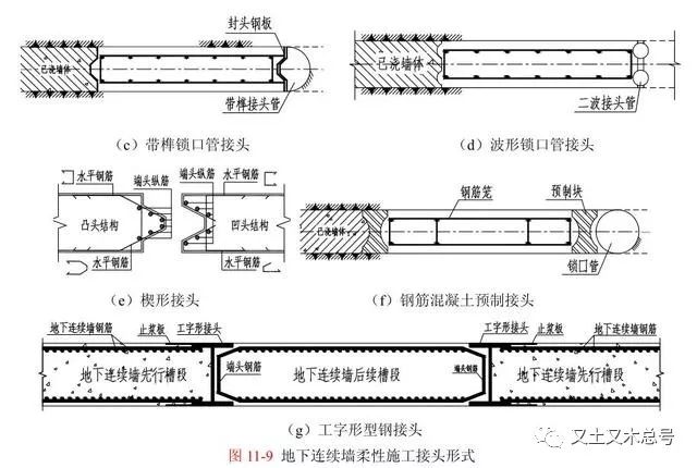
Reinforcement cage of diaphragm wall is composed of longitudinal reinforcement, horizontal reinforcement, sealing reinforcement and structural reinforcement
.
The second confined aquifer of (8B) silt layer is distributed about 40m below the ground
.
Calculation of internal force and deformation the calculation of internal force and deformation of diaphragm wall as the retaining structure of foundation pit is the plane elastic foundation beam method, which is easy to calculate and can be applied to most conventional projects; for deep foundation pit with obvious spatial effect, the spatial elastic foundation plate method can be used for underground connection The calculation of internal force and deformation of continuous wall; for complex foundation pit engineering, continuous medium finite element method should be used to calculate
.
The internal force and deformation of the wall should be calculated according to the beam and slab layout of the underground structure of the main project, construction conditions and other factors, reasonably determine the support elevation and layered excavation depth of the foundation pit and other calculation conditions, and select the calculation mode according to the actual state inside and outside the foundation pit, consider the layered excavation and support of the foundation pit, as well as the sequence and space of the working conditions such as replacing and removing the support The continuous and complete design calculation is carried out under various working conditions
.
4、 Design structure of diaphragm wall 1
.
The thickness of the cylindrical diaphragm wall of the shin Fung Chau underground substation in Tokyo Bay, Japan, has reached 2.40 M
.
If the penetration depth of diaphragm wall determined according to the waterproof requirements is greater than the penetration depth determined according to the stress and stability requirements, in order to reduce the economic investment, plain concrete can be used for the deepened part of diaphragm wall to meet the waterproof requirements
.
2
.
As a waterproof curtain, the penetration depth of diaphragm wall should be determined according to the requirements of groundwater control
.
The foundation pit does not meet the stability requirements of confined water inrush
.
The longitudinal reinforcement is evenly distributed along the wall body, and can be distributed in sections along the depth of the wall according to the stress.
.
The strength mainly refers to the horizontal and vertical section bearing capacity of the wall and the vertical foundation bearing capacity; the deformation mainly refers to the horizontal deformation of the wall and the vertical deformation as the vertical bearing structure; the stability mainly refers to the overall stability as the retaining structure of foundation pit The stability calculation method includes the stability against overturning, uplift and seepage
.
Generally speaking, the width of the wall plate straight groove section should not be greater than 6m, and the total width of the T-shaped and broken line groove sections should not be greater than 6m
.
2
.
Therefore, the requirements of retaining and water resisting should be considered in the depth of the diaphragm wall
.
Therefore, considering the factors of stability and confined water isolation, the diaphragm wall is inserted 23.7m below the base, and according to the requirements of stress and stability, the reinforced concrete is used in the range of 17.2m below the base, and the plain concrete section is used as the water curtain in the section of 17.2-23.7m below the base
.
According to the environmental protection requirements of the base, it is necessary to take partition measures
.
In the foundation pit engineering, the diaphragm wall is not only used as the stress structure to bear the lateral water and soil pressure, but also has the function of water resisting
.
The bottom of diaphragm wall needs to be inserted into a sufficient depth below the base and into a better soil layer to meet the embedded depth and various stability requirements of foundation pit
.
Source: soil and wood
.
According to the stability, the penetration depth is determined as the enclosure of retaining force
.
The underground continuous wall is used as the retaining structure, and the wall is embedded 19m below the base to meet the stability requirements
.
The joints of wall and groove section shall meet the anti-seepage design requirements, and the anti-seepage grade of diaphragm wall concrete shall not be less than grade S6
.
For example, the excavation depth of Yaohua Road Station comprehensive development project of Shanghai Rail Transit Line 7 is about 20.4m
.
With the development of large-scale trenching equipment and improvement of construction technology, the thickness of diaphragm wall can reach more than 2.0m
.
3、 Calculation of internal force and deformation and checking calculation of bearing capacity 1
.