
1、 Classification of building electrical engineering drawing building electrical engineering drawing is a widely used electrical drawing, which is used to explain the composition and function of electrical engineering in buildings
.
Describe the working principle of electrical equipment, provide installation technical data and use and maintenance basis
.
According to the scale of a building electrical engineering, the number and types of drawings are different
.
The common building electrical engineering drawings are as follows
.
1
.
The contents of the catalogue include serial number, drawing name, drawing number, number of drawings, etc
.
2
.
Design description design description (construction description) mainly describes the basis of electrical engineering design, engineering requirements and construction principles, architectural features, electrical installation standards, installation methods, engineering grade, process requirements and supplementary description of relevant design
.
3
.
The graphic symbols or text symbols used in the system are listed in the form of tables in order to make it easy for readers to understand the sample drawings
.
Usually, the legend only lists some graphic symbols or text symbols involved in this set of drawings
.
4
.
List of equipment and materials list of equipment and materials lists the name, model, specification and quantity of the equipment and materials required for the electrical engineering, which can be used for reference in the design budget and construction budget
.
However, the quantities in the table are generally used as budgetary estimates, not as the basis for the supply of equipment and materials
.
5
.
Electrical general plan electrical general plan is a drawing showing the distribution of power supply and power load on the building general plan, mainly showing the name or purpose of each building, the installed capacity of power load, the direction of electrical lines, the location and capacity of power transformation and distribution devices, and the direction of power supply to the household
.
The general situation of the project can be understood through the electrical general layout, and the distribution of electrical load and power supply device can be mastered
.
General large-scale projects have electrical general plan, while medium and small-sized projects are replaced by power plan or lighting plan
.
6
.
Electrical system diagram electrical system diagram is a drawing that uses light line diagram to show the power supply mode, power transmission, distribution control relationship and equipment condition of electrical engineering
.
It mainly indicates the name, purpose and capacity of each circuit, as well as the specifications and models of main electrical equipment, switching elements, wires and cables, etc
.
From the electrical system diagram, we can see the general situation of the project, the number of loops of the system, the capacity and control mode of the main electrical equipment
.
The electrical system includes power transformation and distribution system diagram, power system diagram, lighting system diagram, weak current system diagram (including communication and broadcasting, cable TV, fire alarm, anti-theft security, microcomputer monitoring, automatic instrument, etc.)
.
7
.
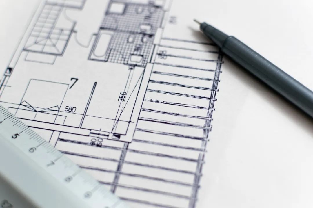
Electrical plan electrical plan is a drawing that represents the layout of electrical equipment, devices and lines, and is the main basis for electrical installation
.
The electrical plan is based on the general plan of the building to draw the installation position and laying method of electrical equipment, devices and lines on the building plan
.
The commonly used electrical plans are: substation plan, power plan, lighting plan, lightning protection plan, grounding plan, various weak current system plan, etc
.
8
.
Equipment layout drawing is a drawing that shows the plane and space position, installation mode and mutual dimension relationship of various electrical equipment and devices
.
It is usually composed of plan, elevation, section, section and various component details
.
The equipment layout is drawn according to the principle of three views
.
9
.
Installation wiring diagram installation wiring diagram, also known as the installation wiring diagram, is used to represent the installation position, wiring mode, wiring mode, wiring location characteristics of electrical equipment, electrical components and lines
.
10
.
Control schematic diagram control schematic diagram is a drawing used to show the control mode and control circuit of electrical equipment and components, mainly showing the start, protection, signal, interlock, automatic control and measurement of electrical equipment and components
.
Through the control schematic diagram, we can know the working principle and control mode of each equipment element, clearly see the action sequence of the whole system, and master the function realization method of the building
.
Control schematic diagram can be used to guide the installation, wiring, commissioning, use and maintenance of electrical equipment and devices
.
Many control schematic diagrams are used, such as power, power transformation and distribution devices, fire alarm, anti-theft security, computer monitoring, automation instruments, elevators, etc
.
control schematic diagrams are also used in more complex lighting and acousto-optic systems
.
11
.
Secondary wiring diagram (wiring diagram) secondary wiring diagram is the supporting drawing of control schematic diagram, which is used to indicate the external wiring of equipment components and the wiring between equipment components
.
According to the wiring diagram, the wiring, control cable, the direction and layout of the control line are controlled by the amplifying guidance system
.
Secondary wiring diagram is used for power, power transformation and distribution equipment, fire alarm, anti-theft security, microcomputer monitoring, automation instrument, elevator, etc
.
Some simple control systems generally have no wiring diagram
.
12
.
Detail drawings are generally used to show the structure or specific installation method of a specific part or equipment element
.
The complexity of the project can be understood through the detail drawing
.
The general non-standard control cabinet, box, detection elements and overhead line installation need to use the detail drawing, the detail drawing usually adopts the standard general atlas, and the section drawing is also a kind of detail drawing
.
2、 Classification of building electrical engineering project 1
.
Interior Engineering, indoor power, lighting electrical lines and other lines
.
2
.
The outdoor power supply lines of external line engineering include overhead power lines and cable power lines
.
The voltage level of these lines is generally below 35KV
.
3
.
The power transformation and distribution project is an indoor and outdoor power transformation and distribution station composed of transformer, high and low voltage distribution cabinet, bus, cable, relay protection and electrical metering equipment and secondary wiring
.
The voltage level of substation is generally below 35KV
.
4
.
Indoor wiring engineering mainly includes wiring of cable pipe, cable tray and trunking, wiring of porcelain bottle, wiring of steel bar, wiring of steel cable, etc
.
5
.
Power engineering all kinds of fans, pumps, elevators, machine tools, cranes and other power equipment (motors) and controllers and power distribution box
.
6
.
Lighting engineering lighting lamps, switches, sockets, fans and lighting distribution box equipment
.
7
.
Lightning protection facilities for buildings, electrical installations and other equipment
.
8
.
Electrical grounding engineering is the working grounding, protective grounding, repeated grounding, lightning protection point grounding and anti-static grounding system of various electrical devices
.
9
.
The electrical engineering of self provided power station and auxiliary equipment of power generation project is generally 400V diesel generator set
.
10
.
Weak current engineering fire alarm system, security system, broadcasting, telephone, closed circuit television system, integrated wiring system, etc
.
If you think it looks good, please click here.
.