

2.
elevation symbol 1.
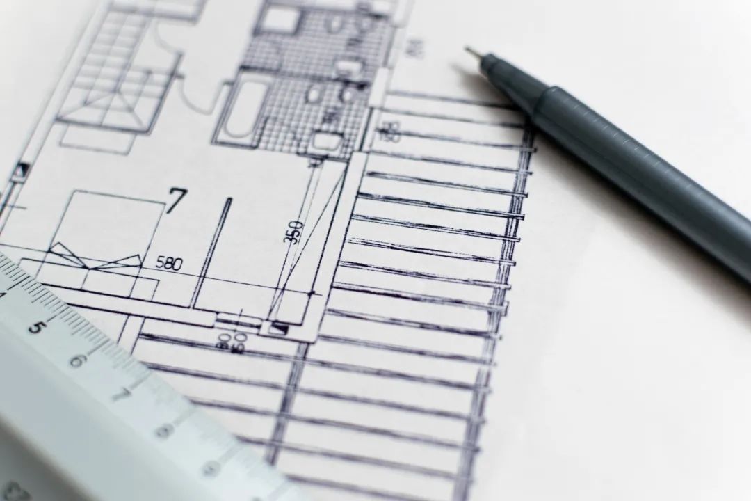
positioning axis 1 Role of positioning axis: (1) important basis for positioning during design and drawing reading; (2) basis for positioning and setting out during construction, such as wall masonry, column and beam pouring, component installation, etc.
Drawing method of elevation symbol and elevation dimensions: (1) isosceles right angle triangle, drawn with thin solid line, and the height on the inclined edge is about 3mm; (2) the outdoor floor elevation symbol in the general plan should be black isosceles right angle triangle; (3) the tip of the symbol should refer to the position of the marked height, generally downward or upward.
Symmetry symbol 1.
The drawing method is drawn according to the percentage of blowing times in all directions according to the local multi-year average statistics.
Purpose for longer components, when the shape in the length direction is the same or changes according to a certain law, they can be disconnected and drawn, and the disconnection shall be represented by connection symbols.
Purpose when the graphic of house construction drawing is completely symmetrical, only half of the graphic can be drawn, and the symmetry symbol can be drawn to save the length of the drawing.
Reading the direction of the wind is from the outside to the center.
Such as the elevation of ring beam bottom surface and beam top surface.
Wind direction frequency rose chart 1.
Compass 1.
Building elevation: refers to the elevation of the surface of components after decoration, such as floor, roof, etc.
V.
Between the two axes, some need to be represented by additional axes, and the additional axes shall be numbered by fractions.
2.
It can be a straight line in the horizontal direction or a straight line and broken line with a length of 30 °, 45 °, 60 ° and 90 ° in the horizontal direction.
The solid line range represents the annual wind direction frequency, and the dotted line range represents the summer wind direction frequency.
2、 Drawing method: (1) the diameter of the circle should be 24mm and drawn with a thin solid line; (2) the width of the tail end of the pointer should be 3mm.
Building communication media ID: jianzhong001 I.
It is similar to the interpretation of the words in the article.
Index symbol and detail symbol 1.
common legend symbols general layout of buildings, common legends of roads and railways, common structures and accessories, common building materials (source: integrated in the network, the pictures and copyright belong to the original author, please contact and delete if there is infringement!) long press the QR code to pay attention to us ▶▶▶。.
Structural elevation: refers to the elevation of the undecorated surface of structural members.
other symbols connection symbols 1.
The slope symbol generally points to the downhill direction (1) when the slope is large, (2) when the slope is general, (3) when the slope is flat and the slope direction is not obvious, (4) the slope sign of road and pavement.
When the North compass needs to be drawn with a larger diameter, the width of the tail of the pointer should be 1 / 8 of the diameter of the circle; (3) the pointer should be painted black, the needle tip points to the north, and note “North” or “n” Word.
III.
2.
(4) the sign and decimal places of elevation numbers (two or three digits) When several elevations need to be marked at the same position.
Purpose} is used to represent the wind direction frequency and house orientation throughout the year in this area.
The number of positioning axes on the plan shall be marked at the bottom and left of the drawing.
The circle and its horizontal diameter shall be drawn with a thin solid line.
2.
Elevation is a dimension form for marking the height direction of buildings, in meters.
II.
Drawing method: draw two parallel lines (thin solid lines) at both ends of the symmetrical center line (thin single point long drawing line).
Break symbol (1) line break: when a figure is broken by a line, its break symbol is a break line, which passes through the broken drawing surface.
The length of the parallel line is 6 ~ 10mm, the spacing is 2 ~ 3mm, and the lengths on both sides of the symmetrical line are equal.
Number of positioning axes (1) The number of horizontal positioning axes shall be written in Arabic numerals from left to right; (2) the number of longitudinal axes shall be written in Latin letters (except I, O and z) from bottom to top.
(2) Curve breaking: for the graphic breaking of circular components, the breaking symbol is curve.
(2) If the index symbol is used to index the detailed section drawing, the cutting position line shall be drawn at the part to be cut, and the index symbol shall be led out by the outgoing line, and the side where the outgoing line is located shall be the projection direction.
For the parts that need to be expressed in detail, the index symbol shall be marked, and the detail shall be marked at the detail drawing Figure symbols.
Such as floor, step top surface and other elevations.
2.
This drawing is applicable to the general drawing (5) Slope signs of pipelines VI.
2、 Drawing method: (1) the index symbol consists of a circle with a diameter of 10mm and its horizontal diameter.
The descriptive connection symbol is a broken line (thin solid line) and indicate the connection number in capital Latin letters.
(3) The outgoing line of the callout detail shall be aligned with the center of the callout symbol (4) For the common outgoing lines leading out several same parts at the same time, the outgoing lines shall be parallel to each other and can also be drawn as radial lines concentrated at one point.
When the slope direction is not obvious, the slope symbol shall be added below the slope number.
(2) the text description should be noted above or at the end of the horizontal line.
4、 Outgoing line 1 Drawing method (1) the outgoing line is used to lead out the word description, dimension marking and detailed index drawing of some parts on the drawing, which shall be drawn with thin solid lines.
Absolute elevation: near Qingdao The mean sea level of the Yellow Sea is the height dimension measured at zero, which is only used in the general plan of the building.
For non load-bearing walls or secondary load-bearing components, additional positioning axes shall be prepared.
The slope is the marking of the inclined part in the construction drawing, It is usually expressed by slope (slope).
Purpose: generally, a compass is painted on the general plan and the ground floor plan to indicate the orientation of the building.
(3) For the axis number on the detail drawing, if the detail drawing is applicable to multiple positioning axes at the same time, the number of relevant axes shall be indicated at the same time, as shown in the figure below.
3.
Function: it represents some important parts in detail, and its detail needs to be drawn for presentation.
it is specified that: for main load-bearing components, horizontal and vertical positioning axes shall be drawn, and axis numbers shall be marked.

Relative elevation: the height dimension measured with the indoor ground at the bottom of the building as the zero point.