
03 finished support construction 3.1 finished support assembly process the finished support assembly process is as follows: read the product technical disclosure, understand the products and precautions, participate in the product installation technical disclosure, be familiar with the product application and installation construction preparation, ensure that the tools and equipment are in place, and read the finished support design drawings, Be familiar with the support layout and structure, prepare the required support materials according to the detailed drawing of single support, assemble the whole support on the ground, connect the whole support at the root point according to the support layout, install the tube bundle and pipeline according to the pipeline layout and support layout, and check all supports after the installation of pipeline.
After installing the whole support on the ground, connect the whole support with the rooting point.
3.4 aerial work tools 1) the hydraulic lift jcpt1823rt aerial work vehicle weighs 8t, the maximum working height is 18m and the platform size is 3.98M × 1.83M, up to 6.57m after extension × 1.83m。 2) The jib truck geniez-60 / 34 has a bearing mass of 227kg, the maximum working height is 20.39m and the platform size is 0.91M × 2.44m, the platform can rotate 180 °, and the climbing capacity is 25%.
The tensile resistance of channel steel base is 11kn.
In order to ensure the strength of the steel structure, the pipe support in large space is not allowed to be directly welded with the steel structure.
Beam clamp 2.2 finished support 2.2.1 finished support is composed of C-shaped steel, steel beam clamp, plastic wing nut, channel steel base, connector, outer hexagon bolt, flange bolt, channel steel end cover, P-shaped pipe clamp, U-shaped pipe clamp, O-shaped pipe clamp, stopper, V-shaped stiffener, U-shaped channel steel gusset plate, square steel clamp, full tooth screw and other accessories.
5) After the support is assembled, a special person shall carry out torque detection on all locking bolts to ensure that all channel steel latches are installed in place, and all fasteners reach the torque value of 40n · m according to the requirements of the design documents.
After calculation, the uniformly distributed load q = 2.474kn/m; The design bearing capacity of steel beam clamp is 4.5kn.
The main truss of the conference hall has a span of 63m and a height of 7m, and the main truss of the banquet hall in the South has a span of 54m and a height of 6m.
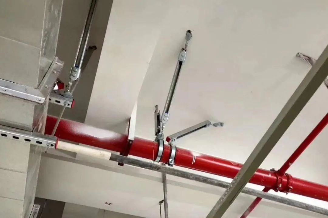
The cross arm at the steel beam connection uses C-section steel and steel beam clamp.
3.3 connection requirements of the support at the rooting point 1) when fixing the rooting of the support with steel beam clamp on the basis of steel structure, the torque of the locking bolt of the steel beam clamp must reach 40n · M.
2.3 the plane layout of the finished support of the integrated pipeline shall be based on the electromechanical deepening design drawings.
3) It is connected with hexagon bolt M12 / 25 through channel steel latch M12.
2) During the assembly of the support, the shaping and positioning shall be carried out first, and then the locking bolts shall be tightened.
In order to prevent damage to the roof structure and waterproof layer, the pipe support is not allowed to drill expansion bolts on the roof concrete floor for rooting.
Therefore, the pipeline construction in high space area is very difficult.
2) Solve the crossing problem between electromechanical pipeline and steel structure truss and triangular support frame.
The conference hall and banquet hall are equipped with central air conditioning system, smoke control system, fire sprinkler system, electrical system, etc.
3.
01 project overview the main structure of a project adopts a large number of tall space steel structures.
When installing the latch, make sure that the latch rotates 90 ° and is fully in place, and the two rows of teeth of the latch are fully engaged with the crimping teeth of the channel steel.
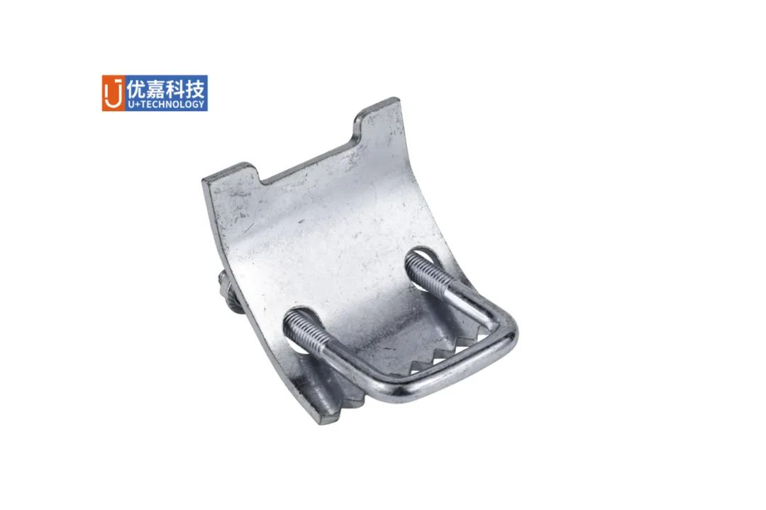
Detailed design of seismic support 02 finished support 2.1 steel beam clamp 2.1.1 basic structure the project selects steel beam clamp as the connection carrier between electromechanical and steel structure.
2.4 multi pipeline integrated support according to the plan of the finished support of the integrated pipeline, draw the section detail of the finished support in the area where the integrated support needs to be set, and clarify the specific method of the support.
The comprehensive plan of the finished support shall be drawn, and the detailed support dimensions shall be marked on the plan considering the pipeline levels and mutual collision.
The electromechanical pipeline support forms of each system shall be determined according to GB / t17116.1-2018 pipe supports and hangers Part 1: technical specifications, GB / t17116.2-2018 pipe supports and hangers Part 2: pipe connecting parts, GB / t17116.3-2018 pipe supports and hangers Part 3: intermediate connectors and building structure connectors, etc.
The steel beam clamp forms vertical bearing capacity and lateral friction after being locked by nuts, so as to form effective fixation.
4) After the support is assembled, the support shall be wiped clean first, plastic channel steel end caps shall be installed on all exposed channel steel end faces, and all supports shall be numbered according to the design drawings.
3) The support shall be installed vertically, neatly and firmly without skew.
3.2 assembly of finished support 1) take the corresponding support materials according to the support design details, and assemble a single support according to the drawing.
During installation, pay attention to the opening direction of channel steel and channel steel base, and install in the correct direction.
Light materials such as siphon rainwater pipe, bridge and short spray branch pipe can be transported vertically by curved boom truck.
3.5 safety construction measures: those close to the floor shall be fixed on the I-steel secondary beam of the top floor, and those close to the steel structure truss can be fixed on the truss nearby..
The tensile design value of M12 plastic wing nut is 5.0kn and the shear design value is 5.0kn.
Stress analysis of the finished support.
3) Design with BIM software, review the layout of finished support in detail, and determine the fixation and installation form of finished support.
The clearance at the bottom of the truss is 14m and the construction height is 20m.
4) The root of the hanger shall be installed according to the construction drawing, the hanger shall be free of bending deformation, the thread shall be complete and well matched with the bolt tube bundle.
5) The bracket shall be shaped and positioned before tightening the locking bolts.
The bolt tightening torque of each connector of the support is 40n · m to prevent loosening.
2.2.2 single pipe support spacing and support selection shall be in accordance with GB50242-2002 code for acceptance of construction quality of building water supply, drainage and heating engineering, cecs183-2015 technical code for siphon roof rainwater drainage system, gb50303-2015 code for acceptance of construction quality of building electrical engineering, gb50243-2016 code for acceptance of construction quality of ventilation and air conditioning engineering T / cecs151-2019 technical specification for grooved connecting pipeline engineering determines the spacing of supports such as smoke control, air conditioning air duct, fire water pipe and electrical bridge.
250mm below floor slab × 600mm I-shaped steel beam with spacing of 3M.
From top to bottom, they are upper spray pipe, siphon rainwater pipe (on the same floor as the upper spray pipe), smoke control air pipe, air conditioning air pipe, electrical bridge (on the same floor as the air conditioner) and lower spray pipe.
The mechanical model is simply supported beam.
The connection between the channel steel latch and the channel steel is the most fundamental fastening element of the finished support system.
2.1.2 the joint rooted with the structure shall be fixed on the structure through steel beam clamp, C-shaped steel, light channel steel base, bolts and other accessories.
The support spacing is set at 3M, the air duct of 1.25m section weighs 61.09kg, and the partial coefficient of load is 1.35.
Both C-section steel and steel beam clamp meet the stress requirements.
The main tall space areas include the North large conference hall (building area 6378m2) for 5500 people and the south large banquet hall (building area 4040m2) for 3000 people.
2) The support spacing shall be set according to the requirements of the design drawings.
in the truss area, two layers of upward and downward sprinkler pipes, smoke control air ducts, air conditioning air ducts, bridges and other electromechanical pipelines shall be installed, with a construction height of 14 ~ 20m.
For heavy materials such as air duct and spray water main pipe, first fix the electromechanical pipeline on the lifting truck and lift it to the required height, then lift the workers and light tools to the operation position with a curved boom truck at both ends of the pipeline, place the pipeline on the support, and connect and fasten it.
1) Optimize the pipeline level.